Two way slab reinforcement detail drawing. 9 inch wall 8 inch base flat top slab xmanhole base to be constructed of class a concrete minimum of 12 inches placed under flow line of pipe xheight of bench to be 08 x.

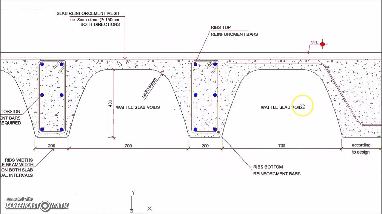
Waffle Slab Cross Section Reinforcement Detail Slab Reinforced Concrete Waffle Ceiling
A Slab depth does not exceed 250mm when the steel grade is 250.

. Flat slab on and larger mhs all joints shall be made watertight using all weather butyl gasket e-z stik or approved equal on inside and. Drawing list revision date drawing no. DETAIL DRAWINGS RASTRA is a stay-in-place insulated concrete form that is structurally strong energy-efficient soundproof resistant to fire high wind mold and.
D Transmission Line Standards Wood-Pole Dead End Details For Overhead Ground Wire. Thickened slab detail drawing Author. The maximum diameter of bar used in slab should not exceed 18 of the total thickness of slab.
Drawings showing the size and location of the reinforcement in a concrete structure. Detail design drawings span carriage way. Fe415 Clear cover.
312 6 inch Residential Frost Wall Integral Slab 4-0. C Slab reinforcement percentage less than 03 100Asbd 03. Minimum reinforcement is 012 for HYSD bars and 015 for mild steel bars.
050615 SD681 HW-D-0585 SHAFT WALL CONCRETE SLAB ASSEMBLY RATING. FLUTED METAL DECK WITH CONCRETE FILL MINERAL. Search for jobs related to Slab reinforcement detail drawing pdf or hire on the worlds largest freelancing marketplace with 19m jobs.
Concrete moisture conditions and drying rate. 36 313 6 inch Residential Frost Wall Brick Crawl Space 4-0. D Transmission Line Standards Concrete Anchors.
Special surface finishes including coatings. Two way slab reinforcement detail drawing pdf. D Transmission Line Standards Anchor Rod Grouting Details.
The imposed loading on the floor is 5 KNm2 and an allowance of 25KNm2 for finishes etc. Use of its drawings computations or for failure resulting from the use of alternate materials or improper application. F Transmission Line Standards Guy Assembly and Details.
210-Special details for seismic design of frames joints walls diaphragms and two-way slabs 21l-Corrosion resistant coatings for reinforcement PART B-RESPONSIBILITIES OF THE DETAILER Chapter 3-Placing drawings pg. Cantilevered RASTRA Slab-to-Wall Connection 1 41 Cantilevered RASTRA Slab-to-Wall Connection 2 42 FOOTING Typical Exterior Footing 1 43. Drawing list revisions 123-sets s110 structural cover sheet sheet nosheet title sheet total symbols and abbreviations for concrete as per aci general existing construction north 1 sd package - 03-30-11 5 symbol legend structural abbreviations s210 foundation plan s501 foundation details s502 steel details s220 roof framing plan dd.
B Slab depth does not exceed 200 mm when the steel grade is 460. Maximum spacing of main bar is. Name signature as sheet a3 size nts gb-dl-01.
This PDF file contains a chapter of 23 pages with various aspects of flat slabs including four example of flat slab design. Dia round pipe in table of quantities riprap at rcp outlets filter fabric dia. UL DETAILS SHEET NO.
This PDF file contains a chapter of 23 pages with various aspects of flat slabs including four example of flat slab design. 6 mm 8 mm 10 mm 12mm and 16mm. X 27 in interior beam dimensions 14 in.
Two-Way Concrete Floor Slab with Beams Design and Detailing Design the slab system shown in Figure 1 for an intermediate floor where the story height 12 ft column cross-sectional dimensions 18 in. 7 inch wall 8 inch base flat top slab 8 ft id. 37 314 6 inch Residential.
A slab is built to provide flat surfaces typically horizontal in building roofs floors bridges and other types of structures. Or span flared end section section b-b. A floor slab in a building where stability is provided by shear walls in one direction N-S.
Sum e clear 10 date. 315-12 31-Definition 32-Scope 33-Procedure 34-Drawing standards 35-Building drawings 36-Highway drawings. Directory of 6 Block Construction Detail Drawings superformicfca CATERGORY 2 Residential Foundation Basement Walls.
M20 Type of steel. 5 inch wall 6 inch base flat top slab 5 ft id. The slab may be supported by walls by reinforced concrete beams normally cast monolithically with the slab.
Its free to sign up and bid on jobs. KEENEBUILDINGsw G0H65H2 Created Date. Prepare a detailed structural drawing of one way continuous slab for a hall of clear dimensions 7m wide and 1177 m long use following data Centre to centre distance of supporting beams 30 m Span of the beams 723m Beams are supported on walls of 023 m thickness Cs of beam 230 x 450 mm Grade of concrete.
Concrete Slab on Grade Grade Beam Detail Fig 1 DWG Concrete Slab on Grade Grade Beam Detail Fig 2 DWG Concrete Slab on Grade Grade Beam Detail Fig 3 DWG Concrete Slab on Grade Grade Beam Detail Fig 4 DWG Griffolyn Repair DWG General Installation Instructions Sheet Pipe Cluster 2 DWGs Vapor Retarder Attachments DWG. Top of footing slab rl 98706 bottom of pcc slab rl 97606 bearing level rl 103706 bearing level rl 103706 bottom of pcc slab rl 102606 existing road level. DETAIL DRAWINGS RASTRA is a stay-in-place insulated concrete form that is structurally strong energy-efficient soundproof resistant to fire high wind mold and.
050615 SD681 HW-D-0585 SHAFT WALL CONCRETE SLAB ASSEMBLY RATING. When above a b and c conditions do not apply bar spacing shall be limited as following Table Table 28 of BS 8110 Part where the reinforcement. The Leading Solar Magazine In India.
It involves the translation of a good structural design from the computer or calculation pad into the. The slab is without drops and is supported internally and on the external long sides by square columns. International Organization for Migration.
Fcu 40 KNm2 fy 460KNm2. X 18 in edge beam dimensions 14 in. Introduction Properties of flat slab Determination of bending moment and shear force The direct design method Equilibrium frame method Slab Reinforcement Example 11 Example 12 Example 13.
Sub-Grade and Sub-Base The sub-grade is the ground on which the floor is built. Vapor retarders - some times referred to as vapor barriers insulation etc. 6 inch wall 8 inch base flat top slab 6 ft id.
X 20 in and unfactored live load 100 psf. ¾Detailing involves thecommunication of the engineers design to the contractors who build the structure. Thickness of the slab is decided based on span to depth ratio specified in IS456-2000.
Typical inlet detail drawing no. The PDF covers the following topics. The diameter of bar generally used in slabs are.
Building Guidelines Drawings Section A General Construction Principles Figures 11 16 Retaining Wall Wall Garage Design

Two Way Slab Reinforcement Details Reinforced Concrete Structural Drawing Concrete Slab

Reinforced Concrete Constant Width Cantilever Slab Detail Reinforced Concrete Concrete Retaining Walls Concrete

Cantilever Veranda Slab With Parapet Wall Detail Reinforced Concrete Concrete Concrete Column

One Way Slab Reinforcement Details Structural Design Engineer Civil Engineering Reinforcement

Waffle Slab Beam Support Reinforced Concrete Slab Reinforcement
Pin On 402

Details Of Slab Reinforcement And Beam Framing Plan Dwg File How To Plan Reinforcement Slab
0 comments
Post a Comment